
Technical Articles
O-Ring Groove Design — Squeeze, Fill, Elongation and Back-Up Rings
Working reference for O-ring groove design: piston, rod, flat-face and dovetail configurations, squeeze and groove fill targets, elongation limits, three-sided grooves and back-up ring selection.
- Reading
- 10 min
- Updated
- 2026-08-08
- Published
- 2026-08-08
- Category
- Technical Articles
The groove is the seal. An O-ring is a commodity; the pocket you machine for it decides whether the joint holds for ten years or weeps in a fortnight. This is the working reference for groove type, dimensions, fill, elongation and back-up rings.
Choosing the groove type
Three arrangements cover almost all practice. Cylindrical grooves seal on the inside and outside diameter surfaces of the ring; flat-face grooves seal on the top and bottom faces.
| Type | Groove machined in | Seals against | Typical use |
|---|---|---|---|
| Piston (external) | The piston / plug | The bore | Cylinder pistons, plugs, spool valves |
| Rod (internal) | The housing or gland | The rod / shaft | Rod glands, shafts, spigots |
| Flat face, internal pressure | One flange face | The opposing face | Covers, caps, ports, manifolds |
| Flat face, external pressure | One flange face | The opposing face | Vacuum chambers, submerged housings |
| Dovetail | Either face | The opposing face | Where the ring must not fall out during assembly |
Cylindrical grooves
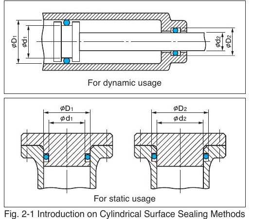
Cylindrical sealing demands more attention to assembly than a flat face does, because the ring has to be pushed over an edge to reach its groove. That is why recommended squeeze for cylindrical duty sits lower than for flat-face duty even though the functional limits are similar: some of the available margin is spent on getting the ring into position undamaged.
For dynamic cylindrical seals, lower squeeze also means lower sliding resistance and less heat generation, so design to the lower half of the range unless the duty is high-pressure.
Flat-face grooves
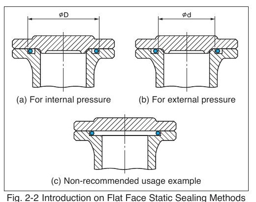
With flat-face joints, position the ring against the wall the pressure will push it towards:
- Internal pressure (pressure inside the ring): match the ring's outside diameter to the groove's outer wall diameter D.
- External pressure (pressure outside the ring): match the ring's inside diameter to the groove's inner wall diameter d.
Never use an open-sided groove where the ring is unrestrained on the pressure side — pressure fluctuation will wear the ring against the edge or work it out of the pocket. Flat-face joints can carry more squeeze than cylindrical ones because assembly is not a constraint, and the extra margin absorbs bolt stretch and flange deformation under load.
Setting the dimensions
- Choose the section (W) first, from the envelope. Thicker is more forgiving.
- Set groove depth (H) to give the target squeeze: H = W × (1 − squeeze).
- Set groove width (G) so that groove fill lands near 75 % and never exceeds 90 %.
- Check elongation — see below.
- Check the clearance gap against pressure and hardness; add a back-up ring if needed.
- Specify surface finish and lead-in chamfers on the drawing, not just the groove.
Standard groove tables for the JIS P/G/V, AS568 and ISO 3601 series already embody these calculations, and you should use them rather than deriving your own wherever a standard size exists. Look up the ring itself with the Sealparts O-ring size search.
Installed elongation and diameter matching
A ring stretched onto a piston loses cross-section as it stretches, which reduces squeeze. A ring compressed into a housing bunches up and can wrinkle. Keep both within bounds:
| Configuration | Target | Limit |
|---|---|---|
| Piston seal (ring stretched over the piston) | Inside-diameter elongation 0–5 % | Never exceed 5 % |
| Rod seal (ring compressed into the housing) | Outside-diameter compression 0–3 % | Never exceed 3 % |
There is a separate absolute limit during fitting. The maximum elongation while installing a ring should stay below 50 % of the material's elongation at break (EB). For a compound with an actual EB of 340 %, that gives an installation limit of about 170 % elongation — meaning a ø20 ring can be stretched over a ø54 diameter during assembly, but no further. Rings stretched near that limit may show slight bulging in the groove for the first few minutes after fitting.
Groove fill in practice
Groove fill = ring cross-sectional area ÷ groove cross-sectional area. Target 75 %, hard limit 90 %. Two things drive it beyond the limit in service:
- Thermal expansion. Elastomers expand roughly an order of magnitude more than steel.
- Fluid swell. A compound with 5–10 % volume swell in the medium consumes the reserve on its own.
If a hot or swelling application must run in an existing groove, the answer is a different compound or a smaller section, not a tighter fit.
Dovetail and three-sided grooves
Dovetail grooves retain the ring mechanically, which is invaluable on inverted or vertical faces during assembly. The cost is a high fill ratio and a risk of scratching or compression-cracking the ring while pushing it in. Typical geometry is a 30°–40° total included angle (15°–20° per side from vertical) with radiused corners, and the ring's diameter centre must line up with the groove's diameter centre.
Three-sided grooves — where the ring is trapped by an adjacent component — compress the ring from three directions and generate relatively high compression set. If you use one, hold D and d to the standard groove table and set the enclosing dimension G to 1.3–1.4 × W.
Back-up rings
When pressure or clearance exceeds the extrusion limit for your hardness, an anti-extrusion (back-up) ring bridges the gap. It always goes on the side away from the pressure; alternating or two-sided pressure needs one on each side.
| Option | Character | Where it suits |
|---|---|---|
| Endless (solid) ring | Most effective, hardest to fit | Assemblies that can be built up in order |
| Bias-cut (scarf) ring | Easy to fit over a shaft, small leak path at the joint | Field service, retrofits |
| Spiral ring | Fits anywhere, moderate performance | Large diameters, awkward access |
| Virgin PTFE | Widest chemical and temperature range, lowest pressure capability | Chemically aggressive, moderate pressure |
| Filled / modified PTFE | Better extrusion and wear resistance at high pressure | Hydraulic duty |
| Polyamide (nylon) | Highest pressure capability; absorbs moisture and can grow dimensionally | High-pressure hydraulics, machined large sizes |
| PEEK | Highest temperature plus high pressure | Hot, high-pressure duty |
Drawing checklist
- Groove depth and width with tolerances, not just nominal.
- Diametral clearance called out, and the pressure it was validated for.
- Surface roughness on the groove bottom, groove sides, sealing face and chamfer.
- Lead-in chamfer angle and length on every edge the ring passes over.
- Corner radii — sharp corners cut rings.
- Back-up ring part, material and orientation, where fitted.
- The standard the ring is called from (JIS B 2401, AS568, ISO 3601) plus the size code.
Frequently asked questions
- How deep should an O-ring groove be?
- Groove depth H = free cross-section W × (1 − target squeeze). For a 3.53 mm section at 20 % squeeze that gives about 2.82 mm. Use the published groove table for the standard series wherever one exists.
- Which side does a back-up ring go on?
- Always on the side away from the pressure, so the O-ring is pushed against it. With pressure from both directions, fit a back-up ring on each side and widen the groove accordingly.
- How much can an O-ring be stretched during fitting?
- Keep installation elongation below 50 % of the compound's elongation at break. For a compound with 340 % elongation that is roughly 170 %. In service, a piston seal should sit at 0–5 % inside-diameter elongation and a rod seal at 0–3 % outside-diameter compression.
- When do I need a dovetail groove?
- When the ring must stay put during assembly — vertical or inverted faces, or where the joint is closed blind. Accept the higher groove fill and take care not to scratch the ring while fitting it.
Related articles
- Technical ArticlesHow an O-Ring Actually Seals — Squeeze, Reaction Force and Pressure EnergisingThe mechanics behind O-ring sealing: installed squeeze, reaction force, pressure energising, groove fill, hardness against extrusion, surface finish targets and compression set.
- Technical ArticlesChamfers, Lead-Ins and O-Ring Installation DamageLead-in chamfer angles and dimensions by O-ring section, assembly rules for threads and cross-drilled ports, and how to tell installation damage apart from genuine service failure.
- StandardsO-Ring Size Standards — ISO 3601, JIS B 2401, AS568 and How to Cross ThemDecode O-ring size codes across ISO 3601, JIS B 2401 P/G/V, AS568 dash numbers, BS 1806 and JASO — with cross-section tolerances and a method for identifying an unknown ring or groove.
- MaterialsO-Ring Material Selection — Temperature, Media and Physical PropertiesContinuous temperature ranges, media compatibility and typical physical properties for NBR, HNBR, FKM, EPDM, silicone, polyurethane and FFKM O-ring compounds, plus hardness and approvals guidance.
Engineering enquiry
Need help specifying or replacing a seal?
Send dimensions, existing markings or a sample. Sealparts engineers respond in 1–3 working days.