
Technical Articles
How an O-Ring Actually Seals — Squeeze, Reaction Force and Pressure Energising
The mechanics behind O-ring sealing: installed squeeze, reaction force, pressure energising, groove fill, hardness against extrusion, surface finish targets and compression set.
- Reading
- 9 min
- Updated
- 2026-08-08
- Published
- 2026-08-08
- Category
- Technical Articles
An O-ring does not seal because it fits the groove. It seals because it is deliberately deformed, and because the fluid it is holding back then helps it deform further. Understanding that two-stage mechanism explains almost every design rule that follows — squeeze, groove fill, hardness, clearance and back-up rings are all consequences of it.
The two-stage sealing mechanism
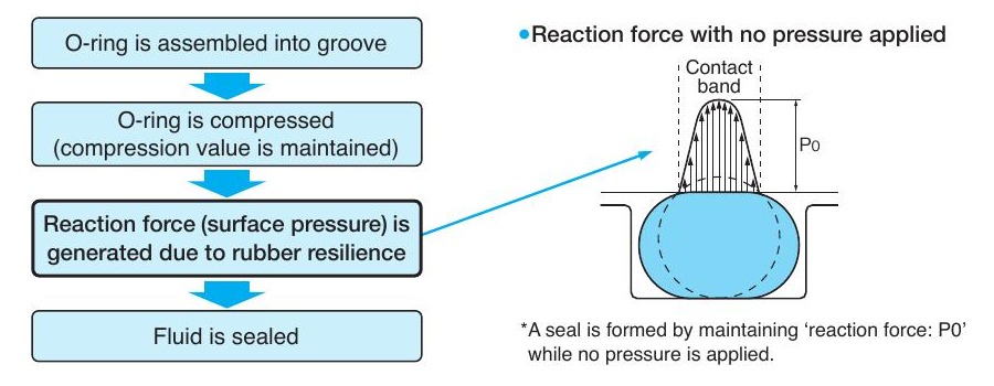
An O-ring is fitted into a groove that is shallower than the ring's free cross-section. Installing it compresses the rubber, and the rubber's own elasticity pushes back against both sealing faces. That reaction force — call it P₀ — produces a contact band of finite width on each face. With no system pressure at all, P₀ alone is what holds the fluid.
When pressure is applied, the ring is pushed across the groove until it lands against the downstream wall. It now behaves less like a spring and more like a confined viscous solid: the applied pressure is transmitted through the rubber and added to the existing contact stress. Contact pressure therefore always exceeds fluid pressure, the contact band widens, and the seal gets tighter as the system works harder. This self-energising behaviour is why an O-ring can hold 400 bar with a few tenths of a millimetre of squeeze.
Squeeze: the single most important number
Squeeze (compression ratio) is the fraction of the free cross-section removed by the groove:
Squeeze % = (W − H) ÷ W × 100, where W is the free cross-section of the ring and H is the groove depth (radial for cylindrical seals, axial for face seals).
Both extremes fail. Too little squeeze and reaction force is insufficient to conform to machining marks, so the joint weeps — particularly on gas. Too much squeeze and the rubber is over-strained: compression set rises sharply, the ring can crack under sustained compression, friction and assembly damage climb, and the groove may over-fill when the ring is heated.
| Configuration | Typical squeeze | Notes |
|---|---|---|
| Cylindrical static (piston / rod, no motion) | 8–25 % | Assembly workability limits the upper end |
| Cylindrical dynamic (reciprocating) | 8–16 % | Lower squeeze reduces sliding friction and wear |
| Flat-face static (flange, cap, port) | 8–30 % | No sliding assembly, so more squeeze is tolerable |
| Vacuum and gas static | 20–30 % | Wider contact band; surface finish is critical |
| Above ~40 % | Not usable | Compression cracking and severe permanent set |
Groove fill and thermal expansion
The groove must be wide enough to accept the ring once it is flattened, plus enough spare volume for thermal expansion and fluid swell. Groove fill is the ring's cross-sectional area expressed as a percentage of the groove's cross-sectional area.
- Target: about 75 %. Comfortable for standard elastomers across normal temperature swings.
- Maximum: 90 %. Beyond this the ring is hydraulically locked; heating or swell has nowhere to go and the groove itself becomes the failure mechanism.
- Below about 60 % the ring can roll or spiral in dynamic duty.
Elastomers expand roughly ten times as much as steel per degree. On a hot application, or with a medium that produces even a few percent volume swell, specify groove fill at the low end.
Why cross-section matters more than diameter
For a fixed squeeze percentage, a thicker ring gives lower compression set and a more stable seal. A 1.78 mm section at 25 % squeeze has far less absolute recovery available than a 5.33 mm section at the same 25 %, so any given amount of thermal drift, groove tolerance or set eats a much larger share of the reaction force.
- Use the thickest section the envelope allows, especially for dynamic duty.
- Thicker sections also resist twisting and spiral failure in reciprocating service.
- Fine sections (1.78–2.4 mm) demand tighter groove tolerances and better surface finish to work reliably.
Hardness, clearance and extrusion
Contact stress and extrusion resistance both rise with hardness, but so do friction and assembly damage. The practical trade-off:
| Hardness | Where it belongs | Watch out for |
|---|---|---|
| 60 | Low pressure, rough or irregular faces, low-temperature duty | Extrudes readily above ~50 bar |
| 70 | The default for most hydraulic and static duty | General purpose; extrusion limit set by clearance |
| 80 | Higher pressure static, larger clearances | Higher friction, less conformability |
| 90 | High-pressure duty, usually with a back-up ring | Assembly damage; needs generous chamfers |
Extrusion is a function of three variables together — pressure, diametral clearance and hardness. As a rough field guide, a 70 Shore A ring will begin to extrude somewhere around 10 MPa with 0.1 mm clearance, while a 90 Shore A ring tolerates roughly twice the pressure at the same gap. Pressure pulsation lowers those limits substantially. If your working point is close to the limit, either close the clearance, raise the hardness, or fit a back-up ring.
Surface finish
The contact faces have to be smooth enough for the rubber to conform to, but not so polished that a dynamic seal cannot retain a lubricant film.
| Surface | Condition | Ra (µm) | Rz (µm) |
|---|---|---|---|
| Groove sides and bottom | Static, no pulsation, flat face | 3.2 | 12.5 |
| Groove sides and bottom | Static, no pulsation, cylindrical | 1.6 | 6.3 |
| Groove sides and bottom | Static with pressure pulsation | 1.6 | 6.3 |
| Groove sides and bottom | Dynamic, no back-up ring | 0.8 | 3.2 |
| Sealing (mating) face | Static, no pulsation | 1.6 | 6.3 |
| Sealing (mating) face | Static with pulsation | 0.8 | 3.2 |
| Sealing (mating) face | Dynamic | 0.4 | 1.6 |
| Lead-in chamfer | All | 3.2 | 12.5 |
Compression set: the slow failure
Compression set is the permanent deformation retained after the load is removed, expressed as a percentage of the original squeeze. At 100 % set the ring has taken the shape of the groove entirely and generates no reaction force at all.
Set accelerates with temperature and with squeeze. A good 70 Shore A NBR will show single-figure set after 70 hours at 100 °C; the same compound at 150 °C is finished. When an application is running near the top of a material's temperature range, set — not chemical attack — is usually what kills the seal first, and the symptom is a weep that appears months after commissioning.
Frequently asked questions
- What squeeze should I design an O-ring to?
- 8–25 % for cylindrical static seals, 8–16 % for reciprocating dynamic seals and 8–30 % for flat-face static joints. Above roughly 40 % the ring is over-strained and risks compression cracking.
- What is groove fill and why does it matter?
- Groove fill is the O-ring's cross-sectional area as a percentage of the groove's cross-sectional area. Aim for about 75 % and never exceed 90 %, so the ring has room to expand with temperature and any fluid swell.
- Does an O-ring seal better at high pressure?
- Yes, up to the extrusion limit. Fluid pressure is transmitted through the rubber and added to the installed contact stress, so contact pressure always exceeds fluid pressure. Past the extrusion limit the ring is forced into the clearance gap and fails.
- Why did my O-ring leak even though it looks undamaged?
- Almost always compression set. The ring has permanently taken the shape of the groove and no longer generates reaction force. Move to a higher-temperature material rather than increasing squeeze.
Related articles
- Technical ArticlesO-Ring Groove Design — Squeeze, Fill, Elongation and Back-Up RingsWorking reference for O-ring groove design: piston, rod, flat-face and dovetail configurations, squeeze and groove fill targets, elongation limits, three-sided grooves and back-up ring selection.
- Technical ArticlesChamfers, Lead-Ins and O-Ring Installation DamageLead-in chamfer angles and dimensions by O-ring section, assembly rules for threads and cross-drilled ports, and how to tell installation damage apart from genuine service failure.
- MaterialsO-Ring Material Selection — Temperature, Media and Physical PropertiesContinuous temperature ranges, media compatibility and typical physical properties for NBR, HNBR, FKM, EPDM, silicone, polyurethane and FFKM O-ring compounds, plus hardness and approvals guidance.
- StandardsO-Ring Size Standards — ISO 3601, JIS B 2401, AS568 and How to Cross ThemDecode O-ring size codes across ISO 3601, JIS B 2401 P/G/V, AS568 dash numbers, BS 1806 and JASO — with cross-section tolerances and a method for identifying an unknown ring or groove.
Engineering enquiry
Need help specifying or replacing a seal?
Send dimensions, existing markings or a sample. Sealparts engineers respond in 1–3 working days.